General information
| B&R ID code | 0x1CEC |
| Status LED |
Yes (color / blink code) 24 VDC OUT power supply (DCOK LED) = Yes (color / blink code) |
| Status indicators | Operating status and power supply |
| Diagnostics | |
| Power supply |
24 VDC OUT: Yes, using LED and software 24 VDC X2X: Yes, using software |
| X2X Link | Yes, using software |
| Overload | Yes, using LED and software (outputs) |
| Power consumption | |
| Internal I/O | Max. 1.5 W (without load) |
| X2X Link power supply | Max. 0.75 W |
| Electrical isolation | |
| Digital outputs - 24 VDC X2X, OUT power supply | No |
| X2X Link - 24 VDC X2X, OUT power supply | Yes |
| X2X Link - Digital outputs | Yes |
| Remote valve terminal connection for 25-pin DSUB multi-pin connection | 16 valves |
| Certifications | |
| CE | Yes |
| UKCA | Yes |
| CRA (Cyber Resilience Act) | In preparation |
| ATEX |
Zone 2, II 3G Ex nA IIA T5 Gc IP67, Ta = 0 - Max. 60°C TÜV 05 ATEX 7201X |
| UL |
cULus E115267 Industrial control equipment |
Circuit
| Bus connection | M12 |
| GND pin | 22, 23, 24, 25 |
| Power supply | M8 |
Interfaces
| User interface | |
| Variant | M12 |
| Type | X2X Link slave |
Digital outputs
| Switching voltage | 24 VDC ±25% |
| Total nominal current | 1.6 A |
| Output circuit | Source |
| Output protection | Protected against short circuit, overload and overtemperature |
| Switching delay | |
| 0 → 1 | Typ. 100 μs / max. 150 μs |
| 1 → 0 | Typ. 125 μs / max. 200 μs |
| Type | High-side driver (source) |
| Max. output current | 0.1 A |
| Max. switching frequency | 100 Hz |
Operating conditions
| Mounting orientation | |
| Horizontal | Yes |
| Vertical | Yes |
| Degree of protection per EN 60529 | IP67 |
Ambient conditions
| Temperature | |
| Operation | 0 to 55°C |
| Storage | -20 to 70°C |
| Transport | -20 to 70°C |
| Relative humidity | |
| Operation | 5 to 95%, non-condensing |
| Storage | 5 to 95%, non-condensing |
| Transport | 5 to 95%, non-condensing |
Mechanical properties
| Note | Order male/female M12/M8 connectors separately |
| Installation | 25-pin DSUB, screw mounting, 4-40 UNC |
| Weight | 125 g |
| Module dimensions including mounting plates | 62 x 70 x 30 mm (H x W x D) |
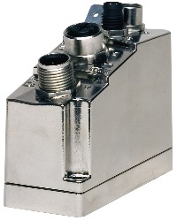
Número de material:
7XV116.50-51Descripción:
Remote valve terminal connection, 16 digital outputs, 0.1 A, 24 VDC, for 25-pin DSUB multipin connector, GND pin 22, 23, 24, 25, X2X Link, electrically isolated, IP67 protection
| Actualizaciones de hardware de Automation Studio | Versión (fecha) | Descargar |
|---|---|---|
| V4.0 HW Upgrade (7XV116.50-51) | EXE / 621 KB |
| Certificados | Versión (fecha) | Descargar |
|---|---|---|
| Safe cutoff of potential groups | PDF / 211 KB |
| Documentación | Versión (fecha) | Descargar |
|---|---|---|
| Compact I/O User's Manual | PDF / 4 MB | |
| XV Users's Manual | PDF / 4 MB |
| M-CAD (plantillas mecánicas) | Versión (fecha) | Descargar |
|---|---|---|
| 3D data DXF / STEP XV IP67 | ZIP / 8 MB |