Short description
| Bus controller | POWERLINK (V1/V2) controlled node with up to 2 slots for interface modules |
General information
| B&R ID code | 0x2268 |
| Status indicators | Module status, bus function |
| Diagnostics | |
| Module status | Yes, using LED status indicator and software |
| Bus function | Yes, using LED status indicator and software |
| Support | |
| Dynamic node allocation (DNA) | Yes |
| Power consumption | |
| Bus | 2 W |
| Additional power dissipation caused by actuators (resistive) [W] | - |
| Certifications | |
| CE | Yes |
| UKCA | Yes |
| CRA (Cyber Resilience Act) | In preparation |
| ATEX |
Zone 2, II 3G Ex nA nC IIA T5 Gc IP20, Ta (see X20 user's manual) FTZÚ 09 ATEX 0083X |
| UL |
cULus E115267 Industrial control equipment |
| HazLoc |
cCSAus 244665 Process control equipment for hazardous locations Class I, Division 2, Groups ABCD, T5 |
| DNV |
Temperature: B (0 to 55°C) Humidity: B (up to 100%) Vibration: B (4 g) EMC: B (bridge and open deck) |
| CCS | Yes |
| LR | ENV1 |
| KR | Yes |
| ABS | Yes |
| BV |
EC33B Temperature: 5 - 55°C Vibration: 4 g EMC: Bridge and open deck |
| KC | Yes |
Interfaces
Electrical properties
| Electrical isolation | POWERLINK isolated from bus and I/O |
Operating conditions
| Mounting orientation | |
| Horizontal | Yes |
| Vertical | Yes |
| Installation elevation above sea level | |
| 0 to 2000 m | No limitation |
| >2000 m | Reduction of ambient temperature by 0.5°C per 100 m |
| Degree of protection per EN 60529 | IP20 |
Ambient conditions
| Temperature | |
| Operation | |
| Horizontal mounting orientation | -25 to 60°C |
| Vertical mounting orientation | -25 to 50°C |
| Derating | - |
| Storage | -40 to 85°C |
| Transport | -40 to 85°C |
| Relative humidity | |
| Operation | 5 to 95%, non-condensing |
| Storage | 5 to 95%, non-condensing |
| Transport | 5 to 95%, non-condensing |
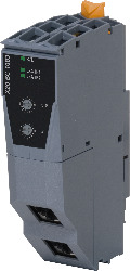
Référence produit:
X20BC1083Description:
- POWERLINK
- I/O configuration and firmware update via the fieldbus
- Integrated hub for efficient cabling
- Up to 2 slots for interface modules
The bus controller makes it possible to connect X2X Link I/O nodes to POWERLINK. It is also possible to operate the X2X Link cycle synchronously 1:1 or synchronous to POWERLINK using a prescaler.
POWERLINK is a standard protocol for Fast Ethernet equipped with hard real-time characteristics. The POWERLINK Standardization Group (EPSG) ensures that the standard remains open and is continually developed:: www.ethernet-powerlink.org.
The bus modules expanded to the left allow connection of up to 2 interface modules in addition to the bus controller.
Accessoires obligatoires
System modules for bus controllers
System modules for expandable bus controllers
| X20BB81 | X20 bus base, for X20 base module (BC, HB, etc.) and X20 power supply module, with one expansion slot for X20 add-on module (IF, HB, etc.), X20 end cover plates (left and right) X20AC0SL1/X20AC0SR1 included |
| X20BB82 | X20 bus base, for X20 base module (BC, HB, etc.) and X20 power supply module, with 2 expansion slots for 2 X20 add-on modules (IF, HB, etc.), X20 end cover plates (left and right) X20AC0SL1/X20AC0SR1 included |
Terminal blocks
| X20TB12 | X20 terminal block, 12-pin, 24 VDC keyed |
Accessoires optionnels
System modules for expandable bus controllers
| X20IF1091-1 | X20 interface module, for expandable bus controller, 1 X2X Link master interface, electrically isolated, order 1x terminal block TB704 separately! |
X20 interface module communication
| X20IF1041-1 | X20 interface module, for DTM configuration, 1 CANopen master interface, electrically isolated, order 1x terminal block TB2105 separately! |
| X20IF1043-1 | X20 interface module, for DTM configuration, 1 CANopen slave interface, electrically isolated, order 1x terminal block TB2105 separately! |
| X20IF1051-1 | X20 interface module, for DTM configuration, 1 DeviceNet scanner (master) interface, electrically isolated, order 1x terminal block TB2105 separately! |
| X20IF1053-1 | X20 interface module, for DTM configuration, 1 DeviceNet adapter (slave) interface, electrically isolated, order 1x terminal block TB2105 separately! |
| X20IF1061-1 | X20 interface module, for DTM configuration, 1 PROFIBUS DP V0/V1 master interface, electrically isolated |
| X20IF1063-1 | X20 interface module, for DTM configuration, 1 PROFIBUS DP V1 slave interface, electrically isolated |
| X20IF10A1-1 | X20 interface module, for DTM configuration, 1 ASi master interface, electrically isolated, order 1x terminal block TB704 separately! |
| X20IF10D1-1 | X20 interface module, for DTM configuration, 1 EtherNet/IP scanner (master) interface, electrically isolated |
| X20IF10D3-1 | X20 interface module, for DTM configuration, 1 EtherNet/IP adapter (slave) interface, electrically isolated |
| X20IF10E1-1 | X20 interface module, for DTM configuration, 1 PROFINET IO controller (master) interface, electrically isolated |
| X20IF10E3-1 | X20 interface module, for DTM configuration, 1 PROFINET IO device (slave) interface module, electrically isolated |
| X20IF10G1-1 | X20 interface module for DTM configuration, 1 EtherCAT master interface, electrically isolated |
| X20IF10G3-1 | X20 interface module for DTM configuration, 1 EtherCAT slave interface, electrically isolated |
| Automation Studio HW Upgrades | Version (date) | Téléchargement |
|---|---|---|
| V2.6 HW Upgrade (X20BC1083) | EXE / 2 Mo | |
| V3.0 HW Upgrade (X20BC1083) | EXE / 2 Mo | |
| V4.0 HW Upgrade (X20BC1083) | EXE / 2 Mo | |
| V6.0 HW Upgrade (X20BC1083) | EXE / 2 Mo |
| Documentation | Version (date) | Téléchargement |
|---|---|---|
| Data sheet X20(c)BC1083 | PDF / 1 Mo | |
| POWERLINK Bus Controller User's Manual | PDF / 3 Mo | |
| X20 Package leaflet ATEX/CSA | PDF / 2 Mo | |
| X20 System User´s Manual | PDF / 45 Mo |
| E-CAD (modèles Electro ou EPLAN) | Version (date) | Téléchargement |
|---|---|---|
| X20 EPLAN P8 from V2.4 | EXE / 160 Mo |
| M-CAD (modèles mécaniques) | Version (date) | Téléchargement |
|---|---|---|
| 3D File STEP/DXF X20BC and X20IF Module | ZIP / 1 Mo |