Short description
| I/O module | 4 digital inputs, 2 digital outputs, 1 analog input, 1 analog output, special functions |
General information
| B&R ID code | 0x24C3 |
| Status indicators | I/O function per channel, operating state, module status |
| Diagnostics | |
| Module run/error | Yes, using LED status indicator and software |
| Analog inputs | Yes, using LED status indicator and software |
| Digital outputs | Yes, using LED status indicator and software (output error status) |
| Power consumption | |
| Bus | 0.01 W |
| Internal I/O | 1.75 W |
| Additional power dissipation caused by actuators (resistive) [W] | - |
| Certifications | |
| CE | Yes |
| UKCA | Yes |
| CRA (Cyber Resilience Act) | In preparation |
| ATEX |
Zone 2, II 3G Ex nA nC IIA T5 Gc IP20, Ta (see X20 user's manual) FTZÚ 09 ATEX 0083X |
| UL |
cULus E115267 Industrial control equipment |
| HazLoc |
cCSAus 244665 Process control equipment for hazardous locations Class I, Division 2, Groups ABCD, T5 |
| DNV |
Temperature: B (0 to 55°C) Humidity: B (up to 100%) Vibration: B (4 g) EMC: B (bridge and open deck) |
| CCS | Yes |
| LR | ENV1 |
| KR | Yes |
| ABS | Yes |
| BV |
EC33B Temperature: 5 - 55°C Vibration: 4 g EMC: Bridge and open deck |
| KC | Yes |
Digital inputs
| Quantity | 4 |
| Nominal voltage | 24 VDC |
| Input characteristics per EN 61131-2 | Type 1 |
| Input voltage | 24 VDC -15% / +20% |
| Input current at 24 VDC | Typ. 3.3 mA |
| Input circuit | Sink |
| Input filter | |
| Hardware | ≤2 µs |
| Software | Default 1 ms, configurable between 0 and 25 ms in 0.2 ms increments |
| Connection type | 1-wire connections |
| Input resistance | Typ. 7.18 kΩ |
| Additional functions | 20 kHz event counting, gate measurement |
| Switching threshold | |
| Low | <5 VDC |
| High | >15 VDC |
| Insulation voltage between channel and bus | 500 Veff |
Event counters
| Quantity | 2 |
| Signal form | Square wave pulse |
| Evaluation | Each negative edge, cyclic counter |
| Input frequency | Max. 20 kHz |
| Counter 1 | Input 1 |
| Counter 2 | Input 3 |
| Counter frequency | Max. 20 kHz |
| Counter size | 16-bit |
Gate time measurement
| Quantity | 1 |
| Signal form | Square wave pulse |
| Evaluation | Positive edge - Negative edge |
| Counter frequency | |
| Internal | 48 MHz, 24 MHz, 12 MHz, 6 MHz, 3 MHz, 1.5 MHz, 750 kHz, 375 kHz, 187.5 kHz |
| Counter size | 16-bit |
| Length of pause between pulses | ≥100 µs |
| Pulse length | ≥20 µs |
| Supported inputs | Input 4 |
Analog inputs
Digital outputs
| Quantity | 2 |
| Variant | Current-sourcing FET |
| Nominal voltage | 24 VDC |
| Switching voltage | 24 VDC -15% / +20% |
| Nominal output current | 0.5 A |
| Total nominal current | 1 A |
| Connection type | 1-wire connections |
| Output circuit | Source |
| Output protection | Thermal shutdown in the event of overcurrent or short circuit, integrated protection for switching inductive loads, reverse polarity protection |
| Diagnostic status | Output monitoring with 10 ms delay |
| Leakage current when the output is switched off | 5 µA |
| RDS(on) | 105 mΩ |
| Peak short-circuit current | <14 A |
| Switch-on in the event of overload shutdown or short-circuit shutdown | Approx. 10 ms (depends on the module temperature) |
| Switching delay | |
| 0 → 1 | <250 µs |
| 1 → 0 | <270 µs |
| Switching frequency | |
| Resistive load | Max. 100 Hz |
| Inductive load | See section "Switching inductive loads". |
| Braking voltage when switching off inductive loads | Typ. 50 VDC |
| Insulation voltage between channel and bus | 500 Veff |
Analog outputs
Electrical properties
| Electrical isolation |
Channel isolated from bus Channel not isolated from channel
|
Operating conditions
| Mounting orientation | |
| Horizontal | Yes |
| Vertical | Yes |
| Installation elevation above sea level | |
| 0 to 2000 m | No limitation |
| >2000 m | Reduction of ambient temperature by 0.5°C per 100 m |
| Degree of protection per EN 60529 | IP20 |
Ambient conditions
| Temperature | |
| Operation | |
| Horizontal mounting orientation | -25 to 60°C |
| Vertical mounting orientation | -25 to 50°C |
| Derating | See section "Derating". |
| Storage | -40 to 85°C |
| Transport | -40 to 85°C |
| Relative humidity | |
| Operation | 5 to 95%, non-condensing |
| Storage | 5 to 95%, non-condensing |
| Transport | 5 to 95%, non-condensing |
Mechanical properties
| Note |
Order 1x terminal block X20TB12 separately. Order 1x bus module X20BM11 separately. |
| Pitch | 12.5+0.2 mm |
Numero materiale:
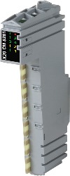
X20CM8281Descrizione:
- Digital and analog channels
- Selectable current and voltage for AI and AO
- Counter functions
The module is a universal mixed module. On this module, digital I/O and analog I/O are combined. A current or voltage signal can be used for the analog I/O as desired. Counter functions on two of the digital inputs expand the range of use.
Accessori obbligatori
| Aggiornamenti HW di Automation Studio | Versione (data) | Download |
|---|---|---|
| V2.6 HW Upgrade (X20CM8281) | EXE / 1 MB | |
| V3.0 HW Upgrade (X20CM8281) | EXE / 2 MB | |
| V4.0 HW Upgrade (X20CM8281) | EXE / 1 MB |
| Documentazione | Versione (data) | Download |
|---|---|---|
| Data sheet X20CM8281 | PDF / 1 MB | |
| X20 Package leaflet ATEX/CSA | PDF / 2 MB | |
| X20 System User´s Manual | PDF / 45 MB |
| E-CAD (Electro o EPLAN Template) | Versione (data) | Download |
|---|---|---|
| X20 EPLAN P8 from V2.4 | EXE / 160 MB |
| M-CAD (Mechan. Template) | Versione (data) | Download |
|---|---|---|
| 3D File DXF/STEP X20 Electronic module | ZIP / 10 KB | |
| 3D File STEP X20 I/O-Slice | ZIP / 872 KB | |
| Dimensions PDF X20 Electronic module | PDF / 3 KB |